Kubernetes: A hybrid Calico and Layer 2 Bridge+DHCP network using Multus

This article is part of the Home Lab series.

    Previously in my Home Lab series, I described how my home lab Kubernetes clusters runs with a DHCP CNI–all pods get an IP address on the same layer 2 network as the rest of my home and an IP from DHCP. This enabled me to run certain software that needed this like Home Assistant which wanted to be able to do mDNS and send broadcast packets to discover device.

    However, not all pods actually needed to be on the same layer 2 network and lead to a few situations where I ran out of IP addresses on the DHCP server and couldn’t connect any new devices until reservations expired:

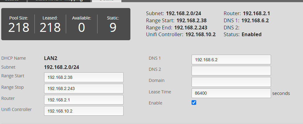
    My DHCP IP pool completely out of addresses to give to clients

    I also had a circular dependency where the main VLAN told clients to use a DNS server that was running in Kubernetes. If I had to reboot the cluster, my Kubernetes cluster could get stuck starting because it tried to query a DNS server that wasn’t started yet (For simplicity, I use DHCP for everything instead of static config).

    In this post, I explain how I built a new home lab cluster with K3s and used Multus to run both Calico and my custom Bridge+DHCP CNI so that only pods that need layer 2 access get access.

    I wanted to move the K8s pods into a separate IP pool and VLAN so I could reduce the blast radius of something going wrong.

    If you’re trying to start a K3s cluster (like I am) from scratch, then you may run into issues where the K3s cluster that Rancher provisions won’t start without a working CNI. If this happens, check out my other post on how to install the CNI.

    Network Configuration

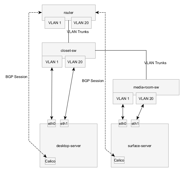
    I created a new VLAN (ID 20) and trunked this VLAN to my router and all switches and configured the router as a DHCP server and enabled it to route traffic between VLANs and the internet.

    I tried trunking the VLAN 20 (and left the default VLAN as untagged) to both computers, however I ran in to an issue where the Surface Dock 2 Ethernet adapter wouldn’t work because it couldn’t receive ARP packets from certain devices on the network on the VLAN tagged adapter. This didn’t make any sense because it was able to get an IP address from DHCP.

    The router wasn’t able to send ARP responses/queries to the VM, but other machines on the network were able to. Logically the only difference I saw was the packet lengths, packets were always less than 64 bytes, but Ethernet is supposed to pad all bytes to a minimum of 64 bytes. This didn’t make any sense, so instead I bought a USB-Ethernet adapter for this computer and used that for my secondary network.

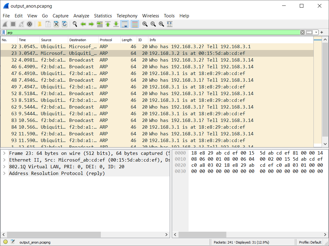
    A packet capture from a tap on the Ethernet cable showing packets, but the responses never made it to the IP stack in the VM

    VM Network Adapter Configuration

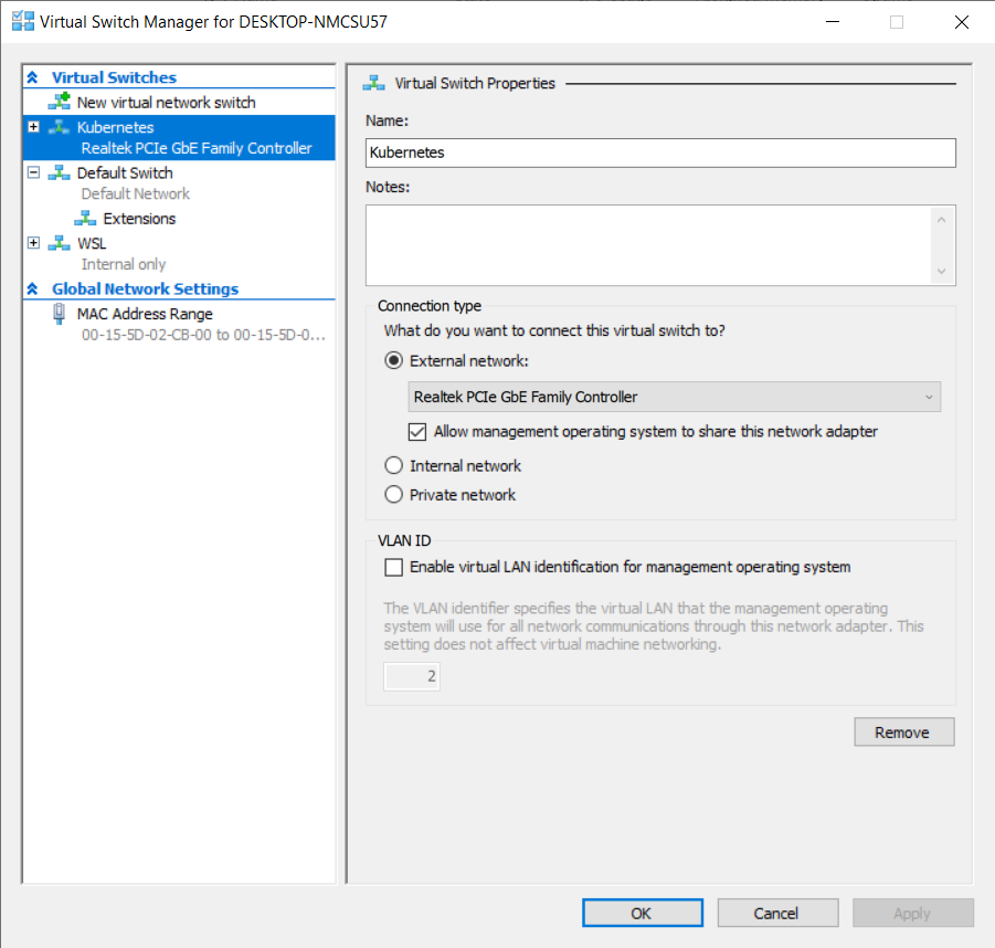
    I’m running my Kubernetes nodes as a Hyper-V VM on two of my Windows computers.

    I previously created a virtual switch (See part #1 if you’re interested in the step by step) for Kubernetes that references my Ethernet adapter:

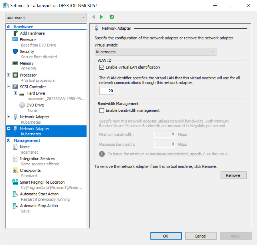
    Then I created a virtual machine that includes two network adapters, both of them bound to that same switch, but one of them included the VLAN Id 20

    Cluster Configuration

    I’m using Rancher’s UI to provision a k3s cluster. By default K3s uses Flannel for it’s networking CNI, but I want Multus so I can use Calico. While creating the cluster, set the agent Env variable, INSTALL_K3S_EXEC to be --flannel-backend=none --disable-network-policy to deploy without the default Flannel cluster, then follow this guide.

    1
    2
    3
    4
    5
    6
    7
    8
    9
    
    apiVersion: provisioning.cattle.io/v1
    kind: Cluster
    metadata:
      name: example
      namespace: fleet-default
    spec:
      agentEnvVars:
        - name: INSTALL_K3S_EXEC
          value: '--flannel-backend=none --disable-network-policy'
    

    OS Network Configuration

    Once Linux is booted in the VM, we can setup the network adapters inside the VM. For more details, see my post on Bridge + Systemd.

     1
     2
     3
     4
     5
     6
     7
     8
     9
    10
    11
    12
    13
    14
    15
    16
    17
    18
    19
    20
    21
    22
    23
    
    $ ls /etc/systemd/network
    10-netplan-eth0.network  10-netplan-eth1.network  cni0.netdev  cni0.network
    
    $ cat /etc/systemd/network/10-netplan-eth0.network
    [Match]
    Name=eth0
    
    [Network]
    Bridge=cni0
    
    $ cat /etc/systemd/network/cni0.netdev
    [NetDev]
    Name=cni0
    Kind=bridge
    MACAddress=00:15:5d:02:cb:09 # Same as eth0 MAC address
    
    $ cat /etc/systemd/network/cni0.network
    [Match]
    Name=cni0
    
    [Network]
    DHCP=yes
    IPv6AcceptRA=yes
    

    The eth1 adapter should be bound to the VLAN 20 network adapter

     1
     2
     3
     4
     5
     6
     7
     8
     9
    10
    11
    12
    13
    14
    15
    16
    
    $ cat /etc/systemd/network/10-netplan-eth1.network
    [Match]
    Name=eth1
    
    [Link]
    MTUBytes=9000 # Optional: Configure Jumbo Frames. All devices on this VLAN need to be configured with this. Since this is limited to just my K8s nodes, this is possible
    
    [Network]
    DHCP=yes
    
    # Without this we end up with two different default routes. For security,  I want to prefer all traffic to pass over the separate VLAN. This VLAN will bypass certain restrictions that I have configured on my main VLAN like forcing all DNS traffic to go through my pi-hole
    
    [Route]
    Destination=0.0.0.0/0
    Gateway=192.168.3.1
    Metric=90
    

    Now I end up with the following route table:

    1
    2
    3
    4
    5
    6
    7
    8
    
    $ ip route
    default via 192.168.3.1 dev eth1 proto static metric 90 onlink
    default via 192.168.3.1 dev eth1 proto dhcp src 192.168.3.2 metric 1024
    default via 192.168.2.1 dev cni0 proto dhcp src 192.168.2.151 metric 1024
    192.168.2.0/24 dev cni0 proto kernel scope link src 192.168.2.151
    192.168.2.1 dev cni0 proto dhcp scope link src 192.168.2.151 metric 1024
    192.168.3.0/24 dev eth1 proto kernel scope link src 192.168.3.2
    192.168.3.1 dev eth1 proto dhcp scope link src 192.168.3.2 metric 1024
    

    Intro to Multus

    Multus is a special CNI that enables you to configure one or more network interfaces on a pod’s network namespace. Each pod always gets the default cluster network/master plugin interface. Then pods can add a special annotation to get more network adapters.

    I’m going to use Calico as my cluster network plugin because it supports BGP and is what I was already using based on previous posts in my series.

    My DHCP CNI will be the optional secondary network attachment.

    Installing Multus

    Unfortunately, Multus doesn’t currently provide any Helm templates. Instead they only provide a YAML file that needs to be modified because it can be used.

    First, download the multus-daemonset.yml from their GitHub repository and save it.

    Find the ConfigMap that defines multus-cni-config. This is what defines the primary network plugin.

    Since I’m using Calico, I used the following ConfigMap:

     1
     2
     3
     4
     5
     6
     7
     8
     9
    10
    11
    12
    13
    14
    15
    16
    17
    18
    19
    20
    21
    22
    23
    24
    25
    26
    27
    28
    29
    30
    31
    32
    33
    34
    35
    36
    37
    38
    39
    40
    41
    42
    43
    44
    45
    46
    47
    48
    49
    50
    51
    52
    53
    54
    55
    56
    57
    58
    59
    60
    61
    62
    63
    
    kind: ConfigMap
    apiVersion: v1
    metadata:
      name: multus-cni-config
      namespace: kube-system
      labels:
        tier: node
        app: multus
    data:
      cni-conf.json: |-
        {
          "name": "multus-cni-network",
          "type": "multus",
          "cniVersion": "0.3.1",
          "capabilities": {
            "portMappings": true
          },
          "delegates": [
            {
              "name": "calico-network",
              "cniVersion": "0.3.1",
              "plugins": [
                {
                  "type": "calico",
                  "datastore_type": "kubernetes",
                  "mtu": 0,
                  "nodename_file_optional": false,
                  "log_level": "Info",
                  "log_file_path": "/var/log/calico/cni/cni.log",
                  "ipam": {
                    "type": "calico-ipam",
                    "assign_ipv4": "true",
                    "assign_ipv6": "false"
                  },
                  "container_settings": {
                    "allow_ip_forwarding": false
                  },
                  "policy": {
                    "type": "k8s"
                  },
                  "kubernetes": {
                    "k8s_api_root": "https://10.43.0.1:443",
                    "kubeconfig": "/etc/cni/net.d/calico-kubeconfig"
                  }
                },
                {
                  "type": "bandwidth",
                  "capabilities": {
                    "bandwidth": true
                  }
                },
                {
                  "type": "portmap",
                  "snat": true,
                  "capabilities": {
                    "portMappings": true
                  }
                }
              ]
            }
          ],
          "kubeconfig": "/etc/cni/net.d/multus.d/multus.kubeconfig"
        }    
    

    Then find the kube-multus-ds DaemonSet and change both the args and the volumes section to look like below. This forces Multus to run before Calico

     1
     2
     3
     4
     5
     6
     7
     8
     9
    10
    11
    12
    13
    14
    15
    16
    17
    
          containers:
          - name: kube-multus
            image: ghcr.io/k8snetworkplumbingwg/multus-cni:v3.9.3
            command: ["/entrypoint.sh"]
            args:
    -         - --multus-conf-file=auto"
    +         - --multus-conf-file=/tmp/multus-conf/0-multus.conf
              - "--cni-version=0.3.1"
    ----
          volumes:
          - configMap:
              defaultMode: 420
              items:
              - key: cni-conf.json
    -           path: 70-multus.conf
    +           path: 0-multus.conf
              name: multus-cni-config
    

    Install Calico

    Now you can install Calico as you normally would. I’ve already got a guide on how I configure Calico in my network here.

    When installing using the Tigera Operator, make sure to configure the nodeAddressAutodetectionV4/V6 settings to use the VLAN 20 (in my case eth1.)

     1
     2
     3
     4
     5
     6
     7
     8
     9
    10
    11
    12
    13
    14
    15
    16
    17
    18
    19
    20
    21
    22
    23
    24
    25
    26
    27
    
    apiVersion: operator.tigera.io/v1
    kind: Installation
    metadata:
      name: default
    spec:
      calicoNetwork:
        bgp: Enabled
        ipPools:
        - blockSize: 26
          cidr: 192.168.7.0/24
          encapsulation: None
          natOutgoing: Disabled
        linuxDataplane: Iptables
        nodeAddressAutodetectionV4:
          canReach: eth1
      cni:
        ipam:
          type: Calico
        type: Calico
      controlPlaneNodeSelector:
        node-role.kubernetes.io/master: "true"
      nodeUpdateStrategy:
        rollingUpdate:
          maxUnavailable: 1
        type: RollingUpdate
      nonPrivileged: Disabled
      variant: Calico
    

    After installing Calico, the cluster should start up correctly and you should be able to launch pods with at least internet connectivity. Next, we need to configure the layer 2 network CNI.

    Install the Layer 2 Bridge CNI

    Now install the DHCP CNI and DaemonSet that I’ve been working on in previous posts (see here):

    github.com/ajacques/cni-plugins/…/dhcp/k8s.yaml:

    kubectl apply -f https://raw.githubusercontent.com/ajacques/cni-plugins/bridge/plugins/ipam/dhcp/k8s.yaml

    Then create a Multus NetworkAttachment:

     1
     2
     3
     4
     5
     6
     7
     8
     9
    10
    11
    12
    13
    14
    15
    16
    17
    18
    19
    20
    21
    22
    23
    24
    25
    26
    27
    
    apiVersion: k8s.cni.cncf.io/v1
    kind: NetworkAttachmentDefinition
    metadata:
      name: layer2-bridge
      namespace: default
    spec:
      config: |
        {
          "cniVersion": "0.4.0",
          "name": "dhcp-cni-network",
          "plugins": [
            {
              "type": "bridge",
              "name": "mybridge",
              "bridge": "cni0",
              "isDefaultGateway": false,
              "uplinkInterface": "eth0",
              "enableIPv6": true,
              "ipam": {
                "type": "dhcp",
                "provide": [
                   { "option": "12", "fromArg": "K8S_POD_NAME" }
                ]
              }
            }
          ]
        }    
    

    Updating the Deployment

    Configuring the deployment to use dual network adapters is easy, add the annotation to the pod annotations not the deployment annotations:

     1
     2
     3
     4
     5
     6
     7
     8
     9
    10
    
    apiVersion: apps/v1
    kind: Deployment
    metadata:
      name: homeassistant
      namespace: smarthome
    spec:
      template:
        metadata:
          annotations:
            k8s.v1.cni.cncf.io/networks: default/layer2-bridge
    

    Solving Network Routing Problems

    As I encountered previously in the series (in Part 5) the containers have an entirely separate route table

    1
    2
    3
    4
    
    sudo ip netns exec {containerns} ip route
    default via 169.254.1.1 dev eth0
    169.254.1.1 dev eth0 scope link
    192.168.2.151 dev net1 scope link
    

    When HomeAssistant tries to send a Wake On Lan packet to turn on my TV at IP address 192.168.2.xy it needs to send a packet to 192.168.2.255. But now our traffic isn’t making it directly out onto the layer 2 network. It matches the default route and goes through the host which is prevents broadcast packets from being broadcast since it’s considered an layer 3 hop and multicast.

    We need to tell the container that it can send traffic destined for the main LAN towards to cni0/eth0/VLAN 1 network adapter.

    I tried creating a custom route by using the redhat-nfvpe/cni-route-override plugin:

     1
     2
     3
     4
     5
     6
     7
     8
     9
    10
    11
    12
    13
    14
    15
    16
    17
    18
    19
    20
    21
    22
    23
    24
    25
    26
    27
    28
    29
    30
    31
    32
    33
    
    apiVersion: k8s.cni.cncf.io/v1
    kind: NetworkAttachmentDefinition
    metadata:
      name: layer2-bridge
      namespace: default
    spec:
      config: |
        {
          "cniVersion": "0.4.0",
          "name": "dhcp-cni-network",
          "plugins": [
            {
              "type": "bridge",
              "name": "mybridge",
              "bridge": "cni0",
              "isDefaultGateway": false,
              "uplinkInterface": "eth0",
              "enableIPv6": true,
              "ipam": {
                "type": "dhcp",
                "provide": [
                   { "option": "12", "fromArg": "K8S_POD_NAME" }
                ]
              },
              {
                "type": "route-override",
                "addroutes": [
                  { "dst": "192.168.2.0/24" }
                ]
              }
            }
          ]
        }    
    

    This allows the container to send traffic through cni0 onto the correct VLAN, but with the wrong source IP and it sends it as 192.168.7.xy (The Calico K8s Pod subnet.) The container route table looks like this:

    1
    2
    3
    4
    5
    
    $ sudo ip netns exec {containerns} ip route
    default via 169.254.1.1 dev eth0
    169.254.1.1 dev eth0 scope link
    192.168.2.158 dev net1 scope link
    192.168.2.0/24 dev net1 scope link
    

    The route is missing a src 192.168.2.xyz to tell the Linux IP stack to use the right source IP address.

    I see the same problem with mDNS traffic that HomeAssistant uses to discover devices on the local network. The following are DEBUG logs showing it’s creating a socket to 239.255.255.250, the multicast IP address for mDNS.

    2022-04-17 00:19:51 DEBUG (MainThread) [async_upnp_client.ssdp] Creating socket, source: (<AddressFamily.AF_INET: 2>, <SocketKind.SOCK_DGRAM: 2>, 17, '192.168.7.253', ('192.168.7.253', 0)), target: (<AddressFamily.AF_INET: 2>, <SocketKind.SOCK_DGRAM: 2>, 17, '239.255.255.250', ('239.255.255.250', 1900))

    Unfortunately, the route-override CNI plugin doesn’t allow us to define the source field on a defined route, so we have to define our own CNI plugin.

    To figure out how to create the right rule, we need the subnet of the loocal network and the network adapter inside the container. Kubernetes stores all of the outputs from the CNI plugins in /var/lib/cni. If we inspect the output file, we can that this information will get passed into a custom CNI:

     1
     2
     3
     4
     5
     6
     7
     8
     9
    10
    11
    12
    13
    14
    15
    16
    17
    18
    19
    20
    21
    22
    23
    24
    25
    26
    27
    28
    29
    30
    31
    32
    33
    34
    35
    36
    37
    38
    39
    40
    
    // cat /var/lib/cni/multus/results/dhcp-cni-network-018684df7309507adb027bbd2b1cec1c06be49d9f1b1ab51601fdb798ce85b7f-net1 | jq
    {
      // ...
      "result": {
        "cniVersion": "0.4.0",
        "dns": {},
        "interfaces": [
          {
            "mac": "00:15:5d:02:cb:09",
            "name": "cni0"
          },
          {
            "mac": "3a:34:17:72:61:28",
            "name": "veth4fd7d3d5"
          },
          {
            "mac": "56:c6:ce:2b:6e:f7",
            "name": "net1",
            "sandbox": "/var/run/netns/cni-090e5f88-9a95-cb98-6cd0-1b8b74ebe32f"
          }
        ],
        "ips": [
          {
            "address": "192.168.2.158/24",
            "gateway": "192.168.2.1",
            "interface": 2,
            "version": "4"
          }
        ],
        "routes": [
          {
            "dst": "0.0.0.0/0",
            "gw": "192.168.2.1"
          },
          {
            "dst": "192.168.2.0/24"
          }
        ]
      }
    }
    

    The full code for the CNI is here. A break down:

    First, we grab a reference to the network namespace for the container (CNI passes this in directly.) linkName will be the name of the container once we’re inside the container and containerNet is 192.168.2.158/24.

    1
    2
    3
    4
    5
    6
    7
    
    // Load Configuration (See GitHub for code)
    
    netns, _ := ns.GetNS(args.Netns)
    defer netns.Close()
    
    linkName := prevResult.Interfaces[2].Name
    containerNet := prevResult.IPs[0].Address
    

    Then swap inside the container network namespace and get a reference to adapter:

    1
    2
    
    err = netns.Do(func(_ ns.NetNS) error {
      containerLink, err := netlink.LinkByName(linkName)
    

    Next, we need to convert the IP address 192.168.2.158/24 to 192.168.2.0/24 since Linux prohibits the former to be used as part of a route and then add it as a route.

     1
     2
     3
     4
     5
     6
     7
     8
     9
    10
    11
    12
    
      // 192.168.2.0/24 dev net1 scope link src 192.168.2.158
      route := &netlink.Route{
        LinkIndex: containerLink.Attrs().Index,
        Scope:     netlink.SCOPE_LINK,
        Src:       containerNet.IP,
        Dst: &net.IPNet{
          IP:   containerNet.IP.Mask(containerNet.Mask),
          Mask: containerNet.Mask,
        },
      }
    
      err = netlink.RouteAdd(route)
    

    Then create a similar route for multicast traffic:

     1
     2
     3
     4
     5
     6
     7
     8
     9
    10
    
      _, i, err := net.ParseCIDR("224.0.0.0/4")
    
      mcastroute := &netlink.Route{
        LinkIndex: containerLink.Attrs().Index,
        Scope:     netlink.SCOPE_LINK,
        Src:       containerNet.IP,
        Dst:       i,
      }
    
      err = netlink.RouteAdd(mcastroute)
    

    This is all taken care of if you use the Docker Image I wrote and update the network attachment:

     1
     2
     3
     4
     5
     6
     7
     8
     9
    10
    11
    12
    13
    14
    15
    16
    17
    18
    19
    20
    21
    22
    23
    24
    25
    26
    27
    28
    29
    30
    
    apiVersion: k8s.cni.cncf.io/v1
    kind: NetworkAttachmentDefinition
    metadata:
      name: layer2-bridge
      namespace: default
    spec:
      config: |
        {
          "cniVersion": "0.4.0",
          "name": "dhcp-cni-network",
          "plugins": [
            {
              "type": "bridge",
              "name": "mybridge",
              "bridge": "cni0",
              "isDefaultGateway": false,
              "uplinkInterface": "eth0",
              "enableIPv6": true,
              "ipam": {
                "type": "dhcp",
                "provide": [
                   { "option": "12", "fromArg": "K8S_POD_NAME" }
                ]
              },
              {
                "type": "route-fix"
              }
            }
          ]
        }    
    

    Now, if we redeploy HomeAssistant it successfully discovers devices on my LAN!

    Conclusion

    In this post, I pulled together several different techniques I applied in previous posts in this series showing how to use Multus to run both Calico and Bridge+DHCP CNIs at the same time. Calico enables us to isolate traffic to a separate VLAN and avoid consuming all the IP addresses in the LAN and Multus with the bridge CNI ensures that software like HomeAssistant, my Sonos control software, and software that uses mDNS can continue to discover devices like they should.

    Copyright - All Rights Reserved

    Comments

    Comments are currently unavailable while I move to this new blog platform. To give feedback, send an email to adam [at] this website url.