In addition to my home lab K8s cluster, I have two dedicated servers that I run in the cloud running a separate Kubernetes cluster. This cluster runs my production servers, like this blog, Postfix, DNS, etc. I wanted to add a VPN between my home network and my prod k8s network for two reasons:
- All data should be encrypted between these networks. While I use HTTPS when possible, some traffic like DNS isn’t encrypted
- My servers outside the NAT should be able to access servers running behind my NAT. I run a Prometheus instance at home that I want my primary Prometheus instance to be able to scrape. Using a VPN can help bypass the NAT and firewall on my router so it can scrape. Additionally, I wanted to be able to access pods directly from my home as needed.
I came across a number of guides for basic Wireguard VPN tunnel configurations which were fine, but they didn’t describe how to solve some of the more advanced issues like BGP routing for MetalLB or how to encrypt traffic to the host itself.
For example, since I have more than one host in my cluster, if I use MetalLB to announce an IP, the Wireguard instance on my router won’t know which host to forward traffic to because it uses the destination IP to pick the encryption key. This results in Wireguard sending traffic possibly to the wrong host.
This blog post will explain everything you need to know to configure a Wireguard VPN that doesn’t suffer from these limitations.
My current setup involves:
- 2 dedicated servers running Kubernetes
- Each server needs an extra IP address that’s not encrypted. IPv6 makes this super easy to assign a secondary IP address that is excluded.
- 1 Ubiquiti EdgeRouter (Alternatives are acceptable provided they support Wireguard VPN and BGP for MetalLB)
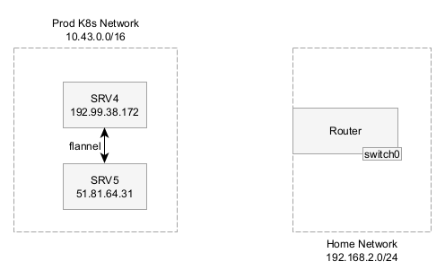
I had two networks: my home network and the prod K8s network. Each K8s node was on a separate dedicated server and had different public IPs, but were part of a Kubernetes overlay network. All devices at IPv6 addresses too.
Wireguard is pretty simple to setup. Each side gets a private key and a public key, you exchange the public keys between nodes, then state what IP addresses should be forward to that endpoint (AllowedIPs).
Where do other guides fall short?
Circular Loops in Routing
I wanted to protect traffic destined to the public IP address of any node (e.g. 192.99.38.172) and traffic to the K8s CIDR (10.43.0.0/16), but I couldn’t set the Wireguard endpoint to also be in the AllowedIPs because the router would try to route the encrypted Wireguard packets back to the Wireguard interface and fail.
It may be possible to fix this issue using router VRFs (Virtual Routing and forwarding) which define separate routing tables for different interfaces. Unfortunately, my current router does not support this feature. If I upgrade, I may revisit this design.
Packet Routing
Wireguard uses the destination IP of every packet to figure out which public key/endpoint it should be forward to. But say you’re using MetalLB in BGP mode to automatically provision Kubernetes Services in the subnet 192.168.10.0/24. I tried setting AllowedIPs=192.168.10.0/24 on both SRV4 and SRV5 and used MetalLB BGP to announce an IP address from the correct node to the router, but with only one Wireguard interface (wg0) on the router side, this didn’t work.
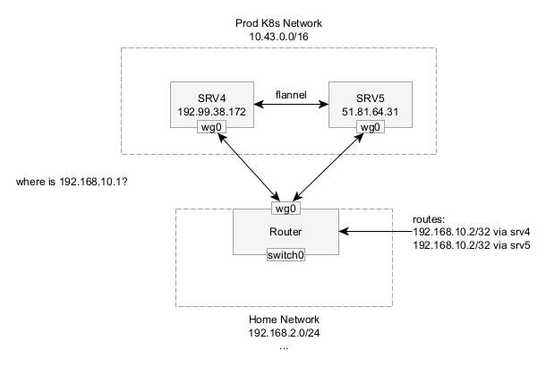
When I attempted to connect to a service IP, the router attempted to send the packet to the correct node following it’s own routing table (see the picture,) but Wireguard ignores that next hop IP address and instead consults the AllowedIPs configuration to figure out where to send it. In this case, both nodes listed this IP address, so Wireguard would send the traffic to the node that appears last in the configuration. If I was using externalTrafficPolicy: Local on the service, then it could hit a node that doesn’t even know how to forward traffic and fail.
High-level Solution
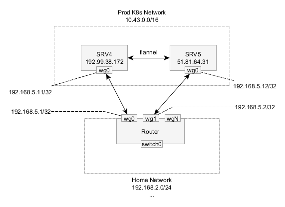
Lets look at my proposed high-level architecture. In this design, the router will get separate Wireguard interfaces for each node pair. Adding more WG interfaces allows us to have overlapping AllowedIPs on each node because the router will run multiple separate instances each with their own config. This enables the router to make its own decisions on which node to forward to before handing it off to Wireguard.
The diagram below shows how this is setup. Each server has one WG interface and the router has multiple WG interfaces. Each interface needs to have a unique /32 IP address in a range. These IP addresses should be private and not overlap with any other IP addresses. We will add more addresses later.
This strategy isn’t without its downsides. One challenge I faced with my specific router software is that there is an option to automatically add the AllowedIPs to the route table (route-allowed-ips). This will conflict with IP addresses that are announced through the tunnel via BGP and we only want certain IPs to be added to the tunnel, specifically the tunnel private IPs (192.168.5.x) and the public IPs (e.g. 192.99.38.172.) A solution will be explained below.
Additionally, each interface requires a separate UDP port to listen on.
Note that if you also have Wireguard connections to other networks or devices, such as a phone, you can reuse one of the existing Wireguard VPN configurations since they won’t have any overlapping IP space. My mobile phone reuses wg0 instead of creating another interface.
Configuration
First step is to prepare the cluster-side software with Wireguard.
Assign a secondary IP address to the host
Since I want to encrypt traffic destined to the public IP address of the nodes, I need to assign a secondary IP address to the interface that isn’t encrypted that the router can forward to.
SRV4 already had two IP addresses: 192.99.38.172 and `2607:5300:60:5fac::/64
To temporarily configure a secondary IP address, I added another IPv6 address to the interface. This will get reset after a restart, but it’s useful for testing.
| |
In Systemd, I ensure the IP address is added upon reboot by editing the network file for this interface.
| |
After this, you should have two IP addresses that can be used to access the server. Only the first IP address will be encrypted, so ensure that you use that when creating DNS records.
Preventing IP fragmentation
Every network interface on all devices have a MTU (Maximum Transmission unit) which defines the maximum size of the IP packet that can be sent across that network. Most of the time when you’re traversing the internet, it’s 1500 bytes.
However, Wireguard works by encapsulating IP packets within aUDP packet that is sent across the internet. A full 1500 byte packet will not fit within a UDP packet. Devices on the networks don’t know what the MTU is (unless you’re using IPv6 which has path MTU detection built-in–another reason to upgrade to IPv6) and when they try to send a full sized packet, the router that’s running the Wireguard VPN will respond with an ICMP Needs Fragmentation packet to let the sender know a new MTU to use.
Unfortunately in my monitoring, the computers didn’t remember this so they would continually try to send too large packets across Wireguard. This reduces performance since it has to keep trying.
Here’s a packet capture showing a multiple computers hit this issue:
| |
There’s a few ways to fix this problem. One way would be to modify the route table on every computer on the network so they don’t ever send too large packet. This solution ensures that all packets are correctly sized (including non TCP protocols like UDP), but that’s too much work.
A common practice is to use TCP MSS (maximum segment size) clamping. Every time a TCP connection is setup, the SYN and SYN-ACK packets include the MSS size. This size dictates how large the TCP payload can be. The MSS is similar to the MTU, except just for the TCP payload.
To understand, we need to look at what a packet looks like. The upstream internet connection starts at an MTU of 1500 Bytes
- 20 bytes for an IPv4 header or 40 bytes for an IPv6 header
- 40 bytes for Wireguard overhead
- 8 bytes for UDP header
- 28 bytes for Wireguard crypto
- -– Encrypted Payload —
- 20 bytes for IPv4 header or 40 bytes for an IPv6 header
- 20 bytes for a TCP header (if you’re using TCP inside the connection)
Wireguard has a default MTU of 1420 which requires an MSS of IPv4:1380 and IPv6:1360. If you want to use the default MTU, feel free to skip directly to the MSS clamping config step and use these MSS clamping values. This value avoids mistakes from people incorrectly calculating their MTUs and encountering strange problems
First we need to calculate the Wireguard MTU. Take the MTU of your uplink interface. Raw Ethernet is generally 1500 bytes, whereas PPPoE might be 1492 bytes, subtract the IP header (20 bytes if you’re using IPv4 as the peer address or 40 bytes if you’re using IPv6 as the peer as is the case in this example), then subtract 8 bytes for UDP.
In my case the MTU is 1500 bytes - 40 bytes - 40 bytes = 1420 bytes.
Now that we have the MTU, the MSS is MTU - 20 bytes for IPv4 - 20 bytes for the inner TCP header. 1452 - 20 (IPv4) - 20 (TCP) = 1380 bytes and 1360 bytes for IPv6 traffic.
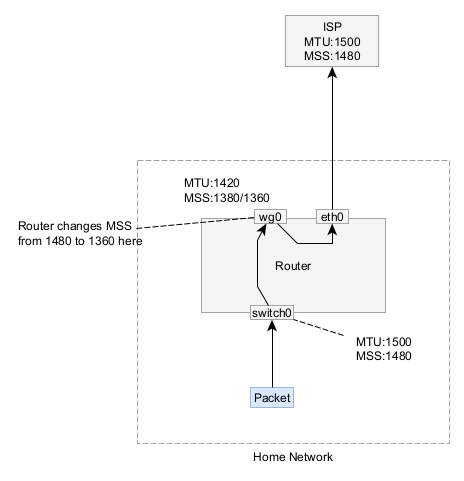
The router modifies the TCP SYN and SYN-ACK packet headers to clamp the MSS to be a max of 1432 bytes.
Take note of all the values that you calculated above. You should have an MTU for the VPN, an MSS value for IPv4, and an MSS value for IPv6.
Deploy Wireguard config files
I’m running multiple worker nodes in my Kubernetes cluster and want each node to run Wireguard, so I created a DaemonSet to deploy the Wireguard software. Each pod will start up using the host network so it can modify the host’s route table.
In this configuration, I define separate files for each server. The script defined in startup.sh loads the config for the correct server and launches the server. There are some security issues with this approach since each server has private keys for all other services that I plan to fix in a future iteration.
Each node gets its own private key since the remote node uses the public key to uniquely identify each server.
Take note in the following example of the AllowedIPs.
| |
This DaemonSet is relatively simple, but the real magic is in the ConfigMap.
| |
Router-side Configuration
Router config may differ depending on what router model you have. I have the Ubiquiti EdgeRouter 12. Wireguard support can be used using the third-party package, wireguard-vyatta-ubnt. This package also supports UnifiOS product lines, however I have not tested this.
Install the software package by following the installation guide.
Then for each server node peer you have configure a Wireguard connection. Replace # with a number for each peer
| |
After all peers are configured
| |
Don’t forget to create any firewall rules or chains that you need to protect traffic from the Kubernetes cluster into your home network. I limit inbound traffic to a few IP ranges.
Routing Allowed IPs
As mentioned earlier, one of the problems with this package is that it creates routes for CIDRs that are also handled by BGP causing conflicts. My strategy is not enable route-allowed-ips and instead configure routes explicitly. This ensures I can easily disable routes if my Wireguard VPN breaks and can exclude the MetalLB range.
| |
Optional - Forward the K8s Pod IP range
| |
MSS Clamping
MSS clamping is configured using firewall rules to modify every packet with the SYN flag set. In the EdgeRouter, the following config will enable MSS clamping.
| |
Conclusion
At this point, your Wireguard VPN should be working. Leave a comment below if this worked or didn’t work for you or if you got it working on any other router types.